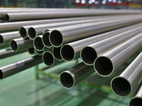
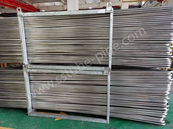
We have been manufacturing stainless steel heat exchanger tube for more than 15 years of experiences, tube material is in an extensive range of austenitic stainless steels, duplex stainless steels as well as nickel alloys, our tubes are designed in welded and drawn condition for heat exchanger system, welded tubes we manufactured are high strength and corrosive resistant properties that maintain optimum performance for heat exchanger, types of heat exchangers include seawater coolers, condensers, evaporators, heaters and reheaters.
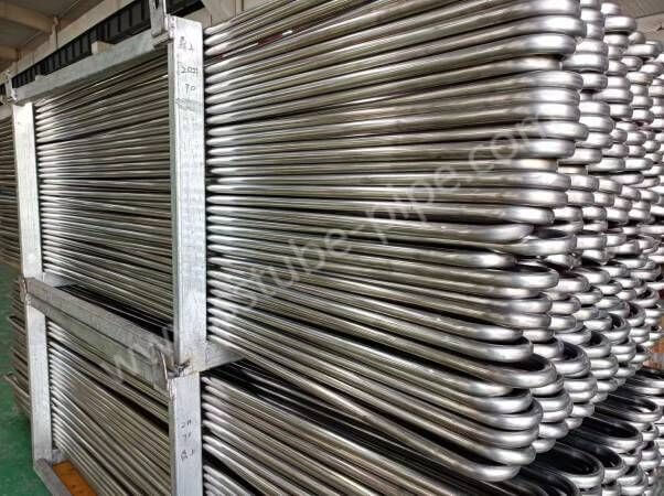
Heat exchanger tube metric sizes from outside diameter 9.53 mm up to 127 mm, imperial sizes from 0.0.375 to 5 inches, and other sizes can be available on request. heat exchanger tubes are supplied in straight-length tubes and U-bent tubes, length can be up to 30 meters.
Features & Benefits
- Material range from common alloys to special alloys
- Wide range of sizes, custom OD and wall
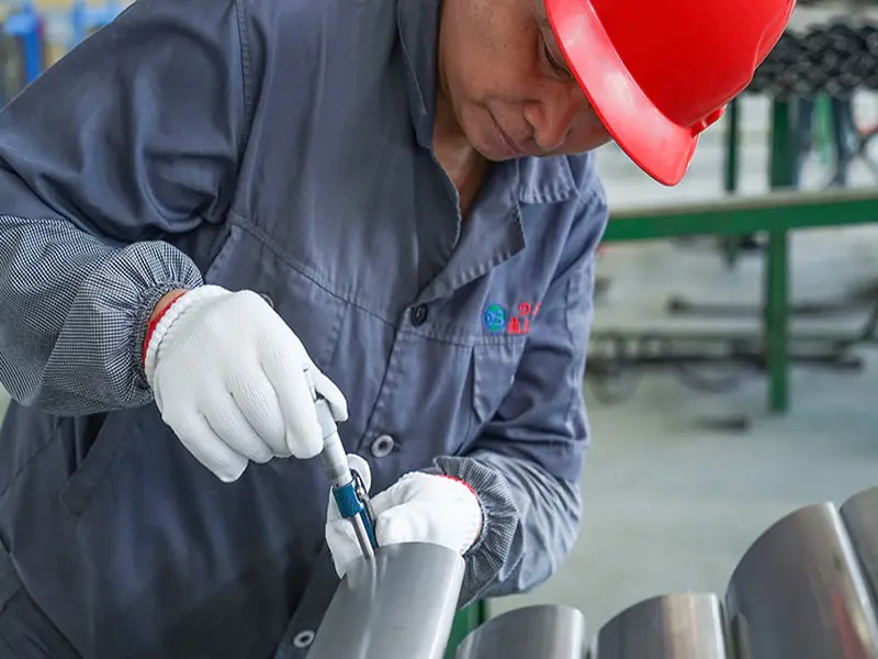
- Tube quality control and inspection
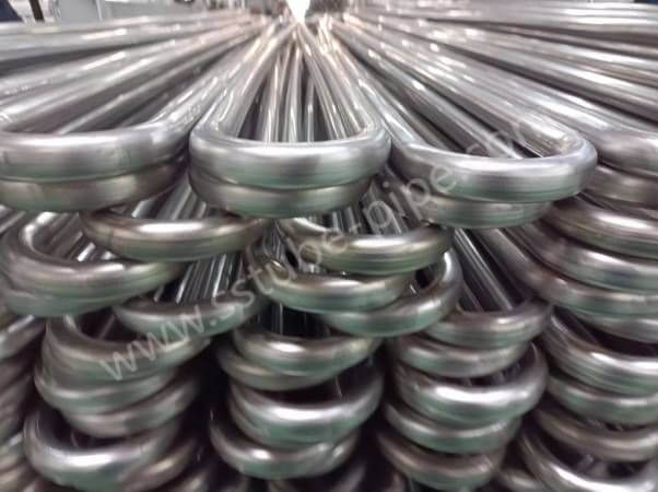
- Straight tube, U bend tube and coil tubing
- Custom mechanical properties
Stainless Stee Heat Exchanger Tube Specifications
| Standard | ASTM A249, ASME SA249, ASTM A268/ASME SA268 |
| Material | TP304/304l, 316/316L, 2205 |
| Tube Type | Welded Tube |
| Finishes | Mill finish |
| Outside Diameter | 9.53 Up To 127 mm |
| Thickness | 0.5 Up To 8 mm |
| U bending | In house |
| Application | Coolers, condensers, evaporators, heaters and reheaters |
Heat Exchanger Tube Material Selection
Stainless steel alloys commonly used for heat exchanger tubes, are separated into three groups based on crystal structure, austenitic, ferritic and duplex stainless. Each group has grades with varying amounts of alloy content and therefore has varying corrosion resistance. Those with low alloy content are lower cost and may be acceptable for applications where high corrosion resistance is not needed.
Typical Grades
| UNS | ASTM | EN steel no. | Steel Name |
| S30403/S30400 | 304L/304 | 1.4307/1.4301 | X2CrNi18-9/X5CrNi18-10 |
| S31603/S31600 | 316L/316 | 1.4404/1.4401 | X2CrNiMo17-12-2/X5CrNiMo17-12-2 |
| S31635 | 316Ti | 1.4571 | X6CrNiMoTi17-12-2 |
| S32100/S32109 | 321/321H | 1.4541/1.4940 | X6CrNiTi18-10 |
| S43035 | 439 | 1.4510 | X3CrTi17 |
| S32205 | 2205 | 1.4462 | X2CrNiMoN12-5-3 |
The tables show our standard materials for heat exchanger tube. Other grades can be offered on request.
Tube standards
| ASTM | ASME | EN |
| A-249 | SA-249 | 10217-7 |
| A-269 | ||
| A-268 | SA-268 | 10217-7 |
| A-688 | SA-688 | |
| A-789 | SA-789 |
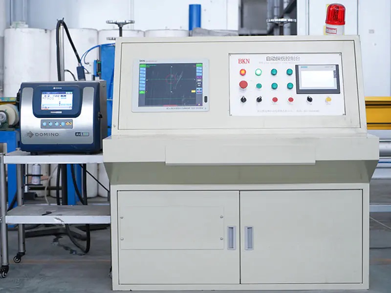
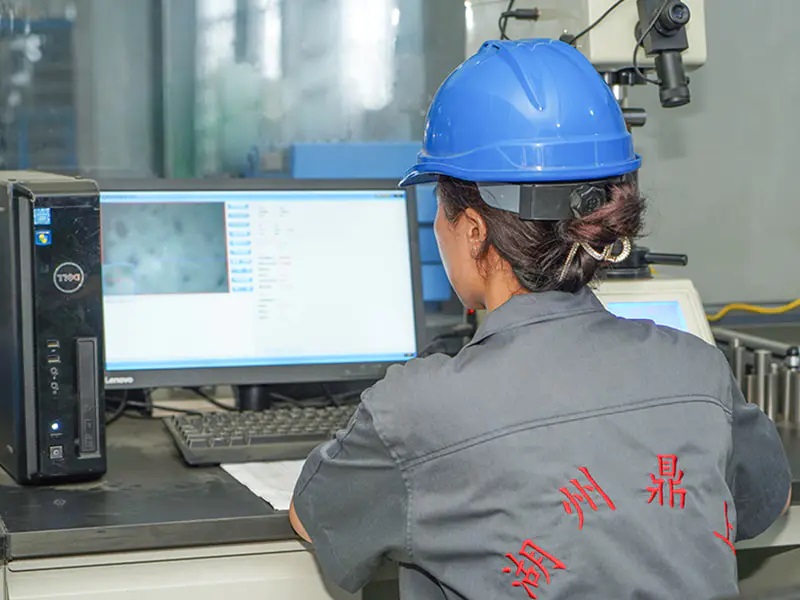
Heat Exchanger Tube Inspection
The tube outside diameter, inside diameter, thickness, and ovality shall be checked before the building of the tube bundle. You need to refer to industry standards to make these measurements and make sure the values fall within the acceptance range.
For example, if your tube material is ASME SA 249, you have to refer to the ASME SA 249.
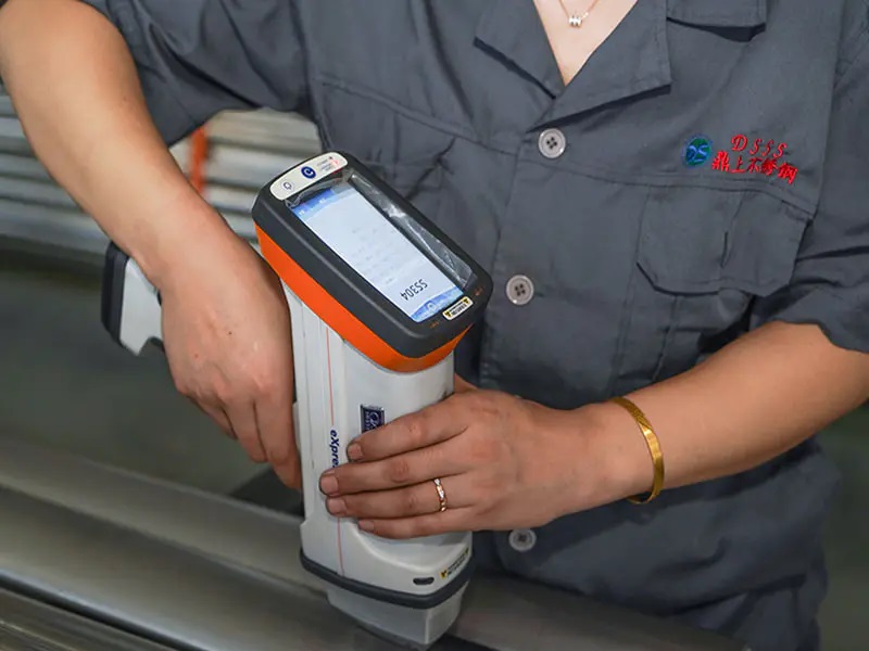
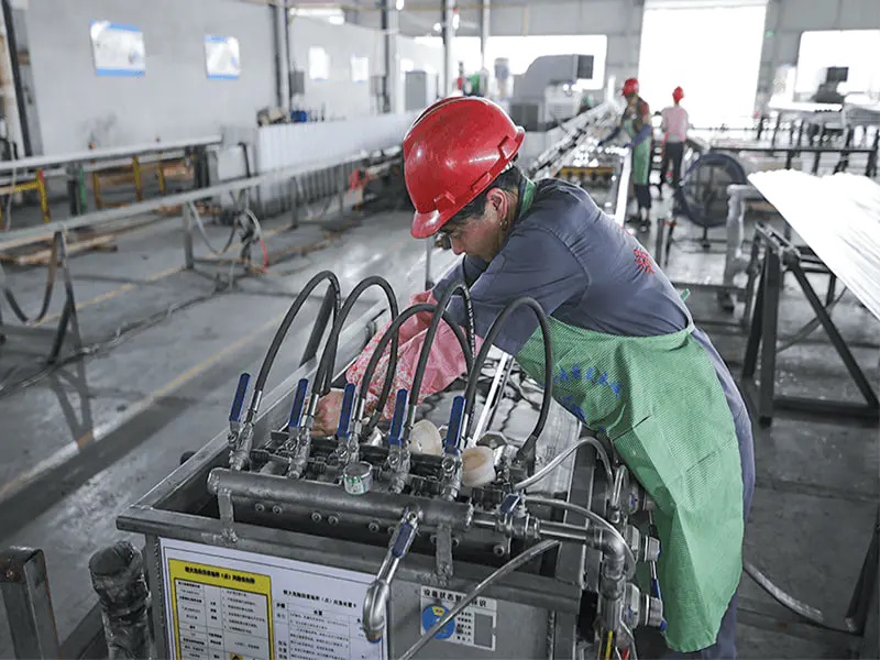
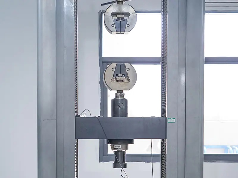
| Standard Testing | Optional Testing |
| Tensile Strength test Flattening test Flare test Flange test Dimensional inspection PMI Hardness test Eddy Current test | Ultrasonic test Hydrostatic test Air Under Water test Grain Size Corrosion test Metallographic Radiographic test |
Heat Exchanger Tube Sizes
Heat-exchanger tubes should not be confused with steel pipe or other types of pipe that are extruded to steel pipe sizes. The outside diameter of heat-exchanger tubes is the actual outside diameter in inches within a very strict tolerance. Heat-exchanger tubes are available in a variety of stainless steel grades. They are obtainable in several wall thicknesses defined by the Birmingham Wire Gauge (B.W.G.), which is usually referred to as the B.W.G. or gauge of the tube.
- OD in mm 12.7- 127 mm
- OD in inch 0.50- 5.00 in.
- Wall thickness in mm 0.89- 8.0 mm.
- Wall thickness in inches 0.035- 0.313 in.
- Max length for 20 meters.
Related References
What is Heat Exchanger?
Heat exchangers are devices that are used to transfer thermal energy from one fluid to another without mixing the two fluids. The fluids are usually separated by a solid wall (with high thermal conductivity) to prevent mixing or they may be in direct contact.
Shell and Tube Heat Exchanger
A Shell and tube heat exchanger consists of a number of tubes placed inside a cylindrical volume (shell). One of the fluids runs through the tubes while the second fluid runs across and along the tubes to be heated.
Shell and Tube Heat Exchanger is one of the most popular types of exchanger due to low purchase and maintenance costs as well as very high heat transfer rate.
The Tubular Exchanger Manufacturers Association, or TEMA, publishes a standard that establishes design, fabrication, tolerances, installation and maintenance of shell-and-tube type exchangers. This standard and the ASME code are the main standards used to design and fabricate exchangers along with any applicable customer specifications. The TEMA standard also defines the classes and main configuration styles of exchangers.
A shell and tube heat exchanger consists of a series of tubes housed within a cylindrical container known as a ‘shell’. All tubes within the shell are collectively termed a ‘tube bundle’. Each tube passes through a series of baffles and tube sheets. One of the tube sheets is fixed and one is free to move, this allows for thermal expansion as the heat exchanger is heated.
The shell and tube heat exchanger consists of four major parts:
- Front Header — this is where the fluid enters the tubeside of the exchanger. It is sometimes referred to as the Stationary Header.
- Rear Header — this is where the tube side fluid leaves the exchanger or where it is returned to the front header in exchangers with multiple tubeside passes.
- Tube bundle — this comprises of the tubes, tube sheets, baffles and tie rods etc. to hold the bundle together.
- Shell — this contains the tube bundle.
Shell and Tube Heat Exchanger Parts
Partition Plate
The partition plate separates the lower and upper halves of the heat exchanger. The partition diverts the flowing medium through the tubes. Inlet / Discharge Inlet or discharge of the fluid medium that flows through the tubes or shell of the heat exchanger.
Housing/Shell
The housing/shell is used to contain the flowing medium and house internal parts. It also serves as a strong structural piece upon which other pieces can be attached. Cover Plate The cover plate is used to seal one end of the shell and prevent leakage.
Gasket
A gasket is placed between two metal surfaces. The gasket is usually constructed of paper or rubber and is ‘squeezed’ between the metals to create a seal. The seal prevents leakage.
The shape of the gasket also prevents leakage around the partition plate.
Stationary Tubesheet
The tubesheet sits within the shell and supports the ends of the tubes. The weight of the tubes is then further supported by the baffles (depending upon the design).
Baffles
Baffles are used to change the directional flow of the fluid medium. Changing the direction ensures an even heat distribution throughout the heat exchanger. Efficiency decreases when flow through the heat exchanger is not evenly distributed.
Bolt
Nuts and bolts are used for securing parts of the heat exchanger. Chosen bolts should have suitable tensile strength and corrosion resistance characteristics. Bolts are the ‘male’ part of a nut and bolt assembly.
Nut
Nuts and bolts are used for securing parts of the heat exchanger. Chosen nuts should have suitable tensile strength and corrosion resistance characteristics.
Nuts are the ‘female’ part of a nut and bolt assembly.
Tie Bars
Tie bars are used as guides for the baffles to ensure no rotational or axial movement of the baffles occurs.
Tubes
One of the fluid mediums flows directly through the tubes whilst the other flows turbulently on the outside. Heat is exchanged between the two mediums due to proximity (heat is exchanged via conduction to the tube walls and then further to the outside medium).
Tubes may range in diameter from 12.7 mm (0.5 in) to 50.8 mm (2 in), but 19.05 mm (0.75 in) and 25.4 mm (1 in) are the most common sizes. The tubes are laid out in triangular or square patterns in the tube sheets, 19.05 mm (3/4″) tends to be the most common size.
U-tube unit can be used to overcome thermal expansion problems and allow the bundle to be removed for cleaning.
Shell
The tubes, baffles and tie bars are all housed within the shell (housing). It is the shell and tube construct which gives this type of heat exchanger its name.
Standard pipe for Shell diameter is normally used for shell diameters up to 610 mm (24″). Above this the shell is made from rolled plate. Typically shell diameters range from 152 mm to 3000 mm (6″ to 120″).
Advantages and Disadvantages of Shell and Tube Heat Exchangers
Advantages
- Cheap compared to plate heat exchangers.
- Relatively simple design and easy to maintain.
- Suitable for higher pressures and temperatures compared to plate heat exchangers.
- Pressure drop is less than a plate heat exchanger.
- Easy to find and isolate leaking tubes.
- Tubes can be ‘double walled’ to reduce the likelihood of the shell side fluid leaking into the tube side fluid (or vice versa).
- Easy to install sacrificial anodes.
- Do not foul as easily as plate heat exchangers.
Disadvantages
- Less efficient than plate heat exchangers.
- Require more space to open and remove tubes.
- Cooling capacity can not be increased, but a plate heat exchanger’s can be.
U-Tube Heat Exchanger
The tube bundle is made of continuous tubes that bend into a “U” shape, and are secured to the shell using one tubeplate. The coolant flows from the top half of the header, through the u-tubes, and then out the bottom half of the header, creating an inherent multi-pass design.
The bend allows for thermal expansion to occur without implementing any kind of expansion joints, as the bend side is free-floating in the shell and has room to expand/contract. They are excellent when using high-temperature differences where expansion is expected.
Common examples of these types of heat exchangers are BEU, BKU and AEU. Because the bundles are removable, the shell side can be cleaned more fully than in fixed-type exchangers. Another benefit with the U-tube configuration is that the tubes can expand and contract freely with temperature differences without causing stress in the shell. The tubes can even expand individually at different rates without any detrimental effects. Expansion joints are never needed with these designs. The bundles can be replaced relatively easily if necessary.
One potential disadvantage to selecting this type of heat exchanger is that it can be hard to clean the inside of the tubes, especially in the bent portion. Removable bundles are not recommended over about 36” diameter because these tube bundles are heavy and difficult to remove and install.
Condensers, Evaporators, and Boilers
Boilers, condensers, and evaporators are heat exchangers which employ a two-phase heat transfer mechanism. As mentioned previously, in two-phase heat exchangers one or more fluids undergo a phase change during the heat transfer process, either changing from a liquid to a gas or a gas to a liquid.
Condensers are heat exchanging devices that take heated gas or vapor and cool it to the point of condensation, changing the gas or vapor into a liquid. On the other hand, in evaporators and boilers, the heat transfer process changes the fluids from liquid form to gas or vapor form.
Heat Exchanger Tube Sizes
| OUTSIDE DIAMETER | WALL THICKNESS | ||||||||||||||||||||
|---|---|---|---|---|---|---|---|---|---|---|---|---|---|---|---|---|---|---|---|---|---|
| mm | 1.2 | 1.5 | 1.7 | 1.8 | 2.1 | 2.4 | 2.7 | 2.8 | 3.0 | 3.4 | 3.8 | 4.0 | 4.2 | 4.8 | 5.2 | 5.6 | 6.4 | 7.1 | 8.0 | 8.3 | |
| in | 0.049 | 0.060 | 0.065 | 0.072 | 0.083 | 0.095 | 0.105 | 0.109 | 0.120 | 0.134 | 0.150 | 0.156 | 0.165 | 0.180 | 0.203 | 0.219 | 0.250 | 0.281 | 0.313 | 0.325 | |
| 12.7 | 0.500 | • | • | • | |||||||||||||||||
| 15.9 | 0.625 | • | • | • | • | • | • | • | • | ||||||||||||
| 19.1 | 0.750 | • | • | • | • | • | • | • | • | • | • | ||||||||||
| 22.2 | 0.875 | • | • | • | • | • | • | • | • | • | • | • | • | ||||||||
| 25.4 | 1.000 | • | • | • | • | • | • | • | • | • | • | • | • | • | |||||||
| 31.8 | 1.250 | • | • | • | • | • | • | • | • | • | • | • | • | • | • | ||||||
| 38.1 | 1.500 | • | • | • | • | • | • | • | • | • | • | • | • | • | • | • | • | • | |||
| 41.3 | 1.625 | • | • | • | • | • | • | • | • | • | • | • | • | • | • | • | • | • | |||
| 42.2 | 1.660 | • | • | • | • | • | • | • | • | • | • | • | • | • | • | • | • | • | |||
| 44.5 | 1.750 | • | • | • | • | • | • | • | • | • | • | • | • | • | • | • | • | • | |||
| 48.3 | 1.900 | • | • | • | • | • | • | • | • | • | • | • | • | • | • | • | • | • | |||
| 50.8 | 2.000 | • | • | • | • | • | • | • | • | • | • | • | • | • | • | • | • | • | • | ||
| 57.2 | 2.250 | • | • | • | • | • | • | • | • | • | • | • | • | • | • | • | • | • | |||
| 60.3 | 2.375 | • | • | • | • | • | • | • | • | • | • | • | • | • | • | • | • | • | • | • | |
| 63.5 | 2.500 | • | • | • | • | • | • | • | • | • | • | • | • | • | • | • | • | • | • | • | |
| 69.9 | 2.750 | • | • | • | • | • | • | • | • | • | • | • | • | • | • | • | • | • | • | • | |
| 73.0 | 2.875 | • | • | • | • | • | • | • | • | • | • | • | • | • | • | • | • | • | • | • | |
| 76.2 | 3.000 | • | • | • | • | • | • | • | • | • | • | • | • | • | • | • | • | • | • | • | |
| 82.6 | 3.250 | • | • | • | • | • | • | • | • | • | • | • | • | • | • | • | • | • | • | • | |
| 88.9 | 3.500 | • | • | • | • | • | • | • | • | • | • | • | • | • | • | • | • | • | • | • | |
| 101.6 | 4.000 | • | • | • | • | • | • | • | • | • | • | • | • | • | • | • | • | • | • | • | |
| 114.3 | 4.500 | • | • | • | • | • | • | • | • | • | • | • | • | ||||||||
| 127.0 | 5.000 | • | • | • | • | • | • | • | • | • | • | • | |||||||||
| 139.7 | 5.500 | • | • | • | • | • | • | • | • | • | • | • | |||||||||
Condensers are heat exchanging devices that take heated gas or vapor and cool it to the point of condensation, changing the gas or vapor into a liquid. On the other hand, in evaporators and boilers, the heat transfer process changes the fluids from liquid form to gas or vapor form.